Tech Talk: Regulator Sizing & Selection
Regulator Sizing & Selection
We recently received a call regarding a regulator that wasn't working correctly. It was operating in a choked flow range, and it wasn't controlling pressure. After some extensive back and forth, we figured out that the regulator in question wasn't appropriately sized for that application. Nailing down proper sizing and selection in the beginning of your project can help ensure you maintain optimal flow curves and save you from future headaches from troublesome problems like that.
Regulator Sizing & Selection Webinar:
Matt and Adam breakdown the ins and outs of regulator sizing & selection.
Upon reading this blog post, you'll have a deeper understanding of:
- Regulator Theory Review
- Regulator Flow Curves
- Flow Coefficient (Cv) of a Regulator
- Regulator Selection
Let's recap with some of the regulator basics.
What Are Regulators?A pressure regulator is a fluid system component designed to control pressure under a given set of system conditions. There are two types of pressure regulators: Pressure regulators control only pressure; they do not control fluid Flow. |
Reviewing Two Types of Pressure Regulators
Pressure reducing regulators (more common of the two) control the downstream or outlet pressure, while back pressure regulators control the upstream or inlet pressure. Both types of pressure regulators operate under similar principles and utilize similar components.

Typically, pressure reducing regulators and back pressure regulators work together to maintain pressure within our processes.
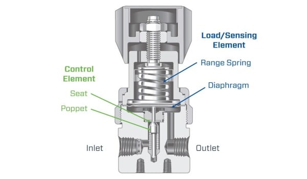
Take a deeper look at a regulator and you'll find we have two primary systems working together to control pressure: The load/sensing element (range spring and diaphragm) and the control element (seat and poppet).
- The control element controls flow and pressure via the seat and poppet. Think of it as the valve within the regulator.
- The load and sensing element is made up of a range spring and diaphragm.
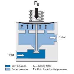
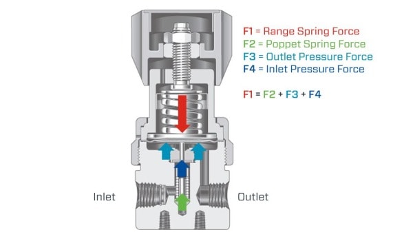
Reviewing The Operating Principle - Balance of Forces
We like to break down how a regulator works into a basic balance of forces equation, similar to a mathematical formula. We have the range spring force that we're controlling, the poppet spring force, the outlet pressure force, and the inlet pressure force. Breaking down the balance of forces can provide insight into why and how some of the regulator performance criteria function the way that they do.
Reviewing Regulator Performance Criteria
- Lockup: The difference in pressure between a flowing and non-flowing condition.
- Choked Flow: When a regulator is fully open, it no longer regulates pressure and acts as a critical orifice.
- Droop: Increased flow results in the set spring extending, which loosens the load force, causing a reduction in outlet pressure.
- Supply Pressure Effect: The change in outlet pressure as a result of a change in inlet pressure.
Shop Pressure Reducing Regulators
The right combination of pressure reducing regulators to fit practically any situation.
Shop Back Pressure Regulators
Back pressure regulators that provide reliable control for your fluid systems.
What Are Regulator Flow Curves?
You may have seen flow curves before in a catalog, whitepaper, or a user manual for a regulator and may have wondered what it is? How is it generated? Well, I got news for you, you're about to find out.
Typically, flow curves are generated in a lab on a test bench. The schematic below shows how one might set that test up. The test regulator is set up to test inlet and outlet pressure. Next in line is the control valve, followed by a flow controller, which allows us to measure the flow rate.
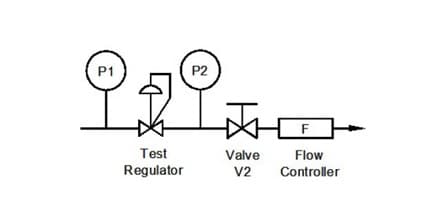
Our flow curve is going to be a plot of outlet pressure vs. flow rate. Looking at the diagram below, the primary points of interest are with the outlet pressure of "P2" and what our flow controller ("F") gives us.
In this test scenario, we'll set our regulator to the measured set point for which we're generating our flow curve. This test is conducted in a static state. We'll set the pressure, and once that pressure is achieved, we'll start to open the flow control valve. We do that until we hit the choked flow scenario, where no more flow goes through that regulator. We run these types of tests for various inlet pressures, set pressures, and regulators.
Where Would You Go to Find Flow Curves?
Swagelok regulator flow curves are documented in our Catalog and Technical Bulletins for both liquid and gas. Want something more than that? Check out our Flow Curve Generator. With this tool, you can generate flow curves for your regulators by specifying your set pressure, inlet pressure, or other parameters.
A Closer Look at a Flow Curve Example:
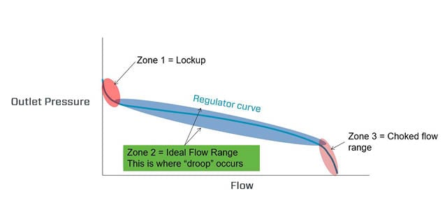
Looking at the below flow curve example, we have the outlet pressure on the vertical axis and the flow rate on the horizontal axis.
The first piece of the flow curve shown is the "Lockup" zone. This is where we start to turn on the flow and see a drop in our outlet pressure as we begin to open up.
On the other end, we have our "choked flow" range. This is where we've maxed out the flow capacity, and the regulator is struggling to control the outlet pressure. The goal is to keep the outlet pressure stable. A slight change in flow rate can cause a sharp change in our outlet pressure.
In between those zones, you'll find the ideal or optimal flow rate range. This is the sweet spot. Selecting a regulator with a flow curve that matches this flow rate is critical to fluid system success.
What Can We Do With a Flow Curve?
There are a few different things that we can do with flow curves to help us better understand regulators that we want to install in our system.
- Look at the flow curves and make sure that we're in that optimal flow range.
- Change parameters in the system and see how the regulator reacts from one flow to another. This lets us figure out what our droop will be and how much our outlet pressure will drop.
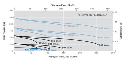
Another Look at a Flow Curve Example:
We're installing a regulator, and we want to understand what our flow rate will be. We also want to know what our droop will be if we increase our flow from 0 to 100 std ft^3/min.
Things we know:
- Set pressure: 250 psig
- Inlet pressure: 507 psig
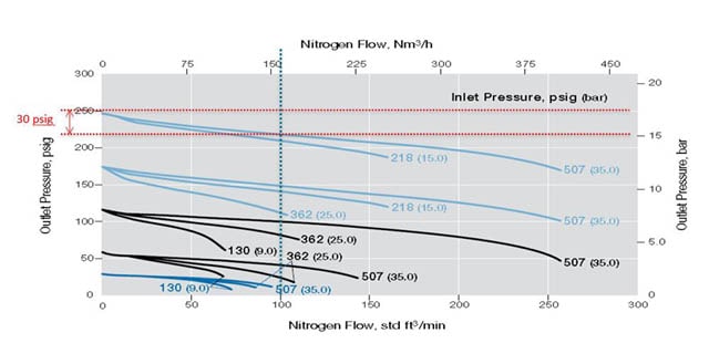
The chart above shows we have a set pressure of 250 PSIG (starting point) and an inlet pressure is 507 PSIG. Note the vertical line demonstrates the intersection at 100 std ft^3/min and two horizontal lines indicating the drop in pressure (30 PSIG from the set). This illustration shows that after turning on our process, we can expect a decrease in 30 PSIG when the flow increases from 0 to 100 std ft^3 min. At this point, it's best practice to adjust the regulator back to where it needs to be.
Flow Coefficient (Cv) of a Regulator
You may have seen the flow coefficient in a catalog or datasheet and thought:
"Perfect! That's an easy way. I know how to size a valve based on a Cv; I can use that to size a regulator!"
But if we look at what the regulator is doing, it's opening and closing our flow rate, kind of like a needle valve. That catalog Cv is documented for a fully open regulator, in other words, the choked flow range. We want to avoid operating the regulator at the listed Cv value. Ideally, we want to look at the flow curves for that regulator. Flow curves will give us a better idea of what the Cv is at during accurate process conditions.
How to Select a Regulator
Here is a quick seven-step process that allows us to check all of our boxes and ensure we're not leaving something out when selecting and sizing regulators.
- Function of Regulator:
Are we looking at a pressure-reducing regulator? Back-pressure regulator? Maybe it's a changeover manifold? What does the regulator need to do to our system?
- Inlet Pressure Range:
What's our nominal inlet pressure? What's our range of inlet pressures? Will we be hooked up to a gas cylinder where we may be going from 3000 psig to 500 psig. Or maybe it's more of a process regulator where our inlet pressure is stable. Will the regulator handle the pressures we provide it? - Pressure Control Range:
We want to look at our set pressure and select a pressure control range that closely matches that set pressure. - Flow Requirements:
Get an idea of what our full flow range needs to be. What is our nominal flow? What's our minimal flow? How about the max? Is there a max flow state that we need to be able to handle with this regulator? - System Compatibility:
Are we worried about corrosion? Is our process fluid compatible with all of the materials in the regulator? Is there a high particulate load in our process stream? - System Functionality:
How does the regulator tie into the rest of the system? Are we keeping the operator safe? - End Connections, Porting, and Mounting:
How are we installing the regulator into our system? How about porting? Are they adequately mounted? These components can be pretty large, so we want to make sure they are properly supported.
Are you struggling to optimize your fluid system? Do you need help selecting a regulator that meets your system's criteria? Our local field engineering team can help. We can come on-site, identify issues, and troubleshoot problems.